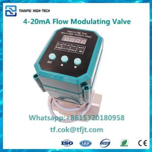
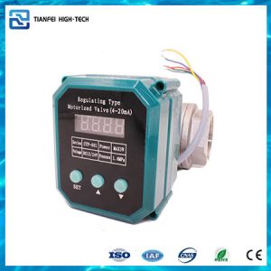
IoT wireless remote control HVAC motorised water valve


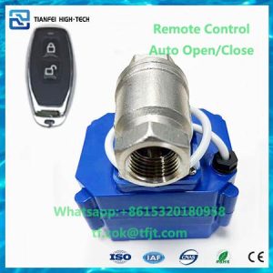
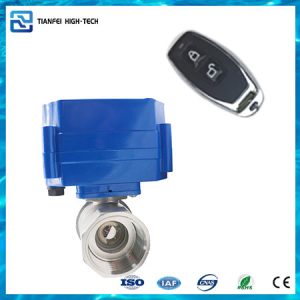
Remote control motorized valves (NB, LoRa)
- Description
- Inquiry
Description


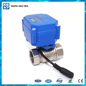
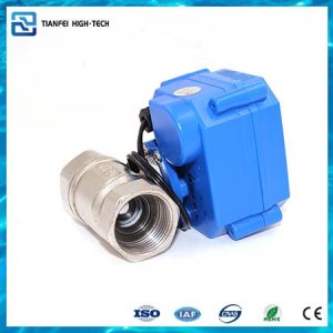
Features of IoT wireless remote control HVAC motorised water valve:
1. Since wireless temperature control valve is divided into wireless temperature controller and smart valve. Therefore controller including motor drive and wireless communication parts.
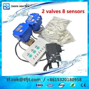
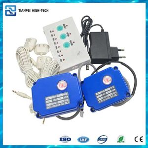
2. The controller senses the environment temperature, and the valve and the thermostat are transmitted by wireless communication module. So that the installation is convenient and the construction is simple
3. Additionally, the controller open and close the valve according to the environment temperature.
4. Because smart valve can transmitted through MBus wires to the collector to control the valve open/close. Granted that to achieve the purpose of indoor thermostat.
5. As a matter of fact, real-time display the indoor temperature, open/close state and the default prompt function.
Applying scenarios of IoT wireless remote control HVAC motorised water valve:
1.For example, water central heating system pipes network
2.Also auto control system for flow measurment
3.Yet Mbus remote control HVAC valve
4. Moreover water save and purification equipment
Main Parameter of IoT wireless remote control HVAC motorised water valve:
| Model Number | TF-W2 |
| Voltage | DC24V |
| Stand-by current | <200mA |
| Ambient temperature | -10-40℃<t<40℃< span=”” style=”box-sizing: border-box; animation-fill-mode: both; word-break: break-word; padding: 0px; margin: 0px;”> |
| Working pressure | Max1.0Mpa |
| Adaptation caliber | DN20-25 |
| Medium Temperature | <100℃ |
| Protection level | IP65 |
| Torque | Max3.5NM |
| Open-Close | <15s |
| Control Mode | MBUS |
| Power | <6W |
Schematic & Dimension of IoT wireless remote control HVAC motorised water valve:

| Brass | Connection | Size | d mm | L mm | H mm | W kg |
| Both female thread | DN20 | 20 | 99 | 55 | 0.431 | |
| DN25 | 25 | 110 | 60 | 0.591 |
Wiring Diagrams of IoT wireless remote control HVAC motorised water valve:
Temperature wireless remote control valve wiring diagram (Voltage:DC24V)

Note:Red and blue wires are for power,green and yellow wires are for MBUS